 |
| V- Mid Frame Mount - USA patent #: US 7,591,202-B2 |
|
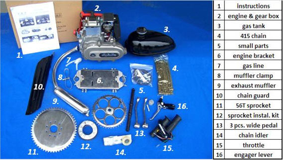
"Do It Yourself" V- Mid Frame Installation Kit
Made for engines with 15.87 Ø x 32 mm PTO shaft. |
 |
11T output drive with freewheel allows a no restriction enhancement when pedaling engine off.
Mechanical aptitude and basic tools required to install. All fasteners are metric.
READ THIS MANUAL THROUGHLY BEFORE ATTEMPTING TO USE THIS PRODUCT: |
Legal Issues:
Most USA State laws stipulate that any motorized vehicle under 50cc engine displacement and 2 hp is legal to operate without a license, registration, or insurance. For complete legal details you should contact your local state authorities. |
| Stage III > 7 bolt gear box housing: |
 |
Stage III –Internal gear and centrifugal clutch parts are same as Stage II except for shift lever & cover.
Stage III also has the added feature of an oil seal at the output shaft. |
|
|
   |
Stage III componets by reference number > 7 bolt gear box: |
#1. Gear box assembly; |
#2. Engine; |
#3. Engine mt. bracket; |
#4. Frame ; |
#5. Chain; |
#6. Chain idler; |
#7. Wheel Sprocket; |
#8A. Cable; |
#9. Handle bar engager lever; |
#10A. Rear GB Hsg; |
#11A. Gear Box cover; |
#12. Centrifugal clutch; |
#13. Cent. C. Bell Gear; |
#14. Engine shaft; |
#15. Big middle gear; |
#16. Center shaft; |
#17. Small middle gear; |
#18. Output shaft; |
#19. Final drive gear; |
#20. Fixed engager /19; |
#21. Sliding engager assy; |
#22A. Shift lever |
#23. Drive sprocket; |
#24A. Cable stop |
#25. Engine holes; |
#26. Attach bolts; |
#27. Not applicable; |
#28. Not applicable; |
#29 FD 19 gear bushing; |
#30A. S/L cover |
#31A. Cover gasket |
#32. S/L Yoak Collar; |
#33. Engager thd. Ring; |
#34A. Lever spring; 2 |
#35A. Output Oil seal |
#36. Stage III cable |
|
 |
DESCRIPTION OF OPERATION
Reference info. can be found at >> www.grubeeinc.com |
| [Para 1] Stage III Gear Box Power Control Systems consist of three major subassemblies. |
(1.) 2 piece Centrifugal Clutch assembly
(2.) Rear housing with all working parts, 3 spur gears, 2 shafts and the S/L cable engager system;
(3.) Gear box cover housing with two ball bearings: |
| When the engine is operating above idle rpm usually about 1800 to 2000 rpm the centrifugal clutch engages the clutch integral bell housing and transmits engine torque through a series of spur gears in a drive train from gear 13 to gear 15, from gear 15 to gear 17 and from gear 17 to the final drive gear 19 to the output drive sprocket 23. |
Donor Bike Specs;
30 to 38mm dia. front down tube and 28mm dia. seat tube works best as a donor bike. Installations have been made on 26” & some 24” bikes; Large bottom hole, approx. 52mm dia. ID is needed to accept our one piece pedal crank. Small bottom hole bikes can use our 3 piece wide pedal crank. It is essential that a donor bike have both front and rear brakes for safe operation but a disc brake on the rear wheel cannot be used. Using a bike with a coaster brake is not recommened because if the pedal chain breaks you have no brake. Do not ride with inadequate brakes! The doner bike needs at least 14” clearance between bottom hole and top tube. Do not use bikes with cheap made rear axles or front forks. Model #1. HD axle kit is recommended. When riding always wear a helmet and abide local and state laws. |
Disclaimer; End user or installer becomes the vehicle manufacture and assumes all laws of the land
including product liability. Do not use this product if you expect otherwise. |
| |
| Frame clearance and engine bracket fit needed; |
 |
| Front and rear bracket to tube fit should look like this. |
 |
 |
| Note; Ball Bearing sizes; #11 Cover has two 6201Z and Engager Housing #10 has 6202Z. |
KIT INSTALLATION INSTRUCTIONS |
 |
 |
 |
| |
 |
Mount bracket to engine loose at first then final tighten after chain alignment; Check threads in bottom mounting holes of engine to see if Metric or English. |
Engine Mounting:
Remove side bolts from the engine mounting plate assembly and separate the plate from the 2 end slide mounts. Attach the engine mount to the bike frame using the included brackets (Figure 14). If you like, you can use strips of old inner tube to protect the frame from damage. If the frame tube is too big for the studs, you will need to remove the studs from the mounts with vise-grips and replace the studs with M6 (6mm) bolts. You may have to cut the bolts to the right length to get them to fit properly. A Dremel with cut-off wheel works well for this.
Make sure that the engine mounting plate sits level position on the tube mounts (Figure 15) and lines up with the side holes. Lift the plate off the mounts Engine must set level for best carburetor operation.
|
 |
 |
| Figure 14. Attach the slide mounts. |
Figure 15. Make sure the plate is level. |
|
| Attach the engine to the plate using the included bolts. Tighten the bolts finger-tight only, for now. Place the engine and plate on the castings. Remove the master link from the engine drive chain with the needle-nose pliers. Put the master link in a bag or other container immediately, before it gets lost! Drape the chain over the rear sprocket and gearbox output sprocket. Pull the chain taut. Check the alignment of the chain from the rear of the bike. The chain should be in alignment with both sprockets. You can adjust the alignment by sliding the engine left or right on the engine plate. If you cannot get the chain aligned properly, you may have to remove the wheel drive sprocket and change its orientation (from concave-in to concave-out. Once you are satisfied with the engine drive chain alignment apply loctite to the side bolts and tighten. You should be able to tighten these bolts from the underside without removing the engine. If the holes don't line up, you can clamp the engine plate to the slide mounts with vise-grips while you install the side bolts. Be very cautious when tightening the side bolts. They will strip the threads in the castings if you over tighten them (over tightening is not covered under warranty). At this time, you can install the muffler and tighten the muffler exhaust pipe flange bolts. |
 |
 |
 |
 |
| Note: To remove gear box cover first pry with screw driver at rear then at front to work cover off gear box. |
|
| The Gear Box centrifugal clutch wotks great with 50 to 80cc 10wt. HT oil. |
|
Good to applly some prelub gear grease before adding 50 to 80cc of high temp. 10wt. machine oil; |
THREE MUFFLER OPTIONS: |
 |
 |
|
| Std. Muffler #12A |
Long Poo Poo pipe #5 |
Fancy Poo Poo Pipe # 6 |
| |
 |
| |
|
 
REFERENCE FOR BOTH STAGE II & STAGE III KITS: |
|
| [Para 1] Warrning: Never release engager lever when engine is above engine idle rpm or damage can possibly occur to drive sprocket and chain due to engagement shock load with a running centrifugal clutch.. |
  gear box gaskets: gear box gaskets: |
| [Para 2] Installation step one: Install centrifugal clutch assembly 12 and bell housing with primary drive gear 13 to a Honda GXH 50 or HuaSheng F142 4 cycle engine output shaft 14 as shown in FIG. 7. |
| |
[Para 3] Installation step two: Install 4 bolt gasket on engine us gasket sealer to hold in place. Attach Rear GB plate housing 10 over the centrifugal clutch assembly; Install two short bolts going through holes 26 approximately midway of the rear GB Plate housing into two corresponding threaded holes 25 on the engine. |
 |
| [Para 4] Note: On some China engines the crankcase screw head on the right side of the flange opening must be modified so it does not hit the gear box at the #16 bearing pocket boss area. To modify, delete the lock washer and file off 1mm from the top of the screw head to gain 2mm total clearance. After installing the gear box check for air gap clearance with a flash light or paper insert. This problem does not seem to occur when using Honda GXH50 engines but always check for clearance after gear box installation. |
| ( Do not grind on the gear box bearing boss: ) Check engine shaft for correct ID. Make sure the output shaft is 15.8 dia x 33.5mm shaft as found on Honda GXH50 model engines. DO NOT RUN THIS KIT on Huasheng engines with smaller DIA. OUTPUT SHAFTS such as the 15mm size as sold by compitiors. |
| BEST Installation for worry free operation and long life: |
|
Use optional HD Axle Kit Model #1.
Use optional 10Th solid gear box output drive sprocket kit.
Use 56T wheel sprocket for all 26” wheels.
Use a 3 brake system with optional dual brake cable throttle.
Use optional dual lever, clutch / brake on left side handle bar. |
 |
 |
| |
Cover gasket shown in place on rear housing plate;
Use RTV gasket sealant to prevent oil / grease leaks: You |
|
| may find the gasket is not need when using RTV and may work better without it. |
| [Para 5] Attach the cover housing 11 having two ball bearings that line up with corresponding shaft 16 & jackshaft 18 in the cast housing 10. Use cover gasket and seal with RTV gasket sealant. If not pre-lubricated from factory apply heavy high temp. grease on gear teeth before installing GB cover plate 11. The GB cover 11 is then tapped into position with a rubber mallet to fit tightly over the cast housing 10 in a recessed lip around the perimeter. After cast housing 11 is in position two long bolts are inserted through the two left side lug mount holes 26 of both the cast housings 10 and 11 and extend into the threaded holes of the engine accessory drive mounting flange 25. Shorter bolts are installed through cast housings 10 & 11 all bolts tighten securely in sequence. After installing gear box on engine and all bolts have been tighened in sequence you can add 50cc to 80cc of 10wt. HT oil. Do not over fill. A little oil is good but too much is bad. A little trial and error is reqiired to get a happy blance. |
| [Para 6] The shift lever 22A with steel cable 8 attached going to hand lever 9 is pre-installed at the factory for ease of installation on the bike handle bar. Next step is to secure cable splice mid bracket. |
 Use plastic ties to secrure cable mid bracket to frame. Use plastic ties to secrure cable mid bracket to frame. |
 |
 |
| |
Push button engager lever opt. dual lever |
|
|
Economy way: Install 56T chain sprocket to bike rear wheel hub. Dish convex side inward, teeth outward. Attach with 9 bolts through 2 half moon bearing plates and 3 banana pieces with rubber gasket next to spokes. ( See More info. below: ) Use locktite on the threads and torque evenly to produce a sprocket installation that does not wobble. If the center hole needs enlarging to fit the axle hub use a machine shop engine lathe to gain best cutting accuracy. If hand grounding with a Dremel tool mark a circle out line using a round pattern such as a piece of PVC pipe and a black marker so your cutting is evenly round. Use of the Model #1. HD axle kit avoids all these problems but is an extra cost option available only from your Shyhawk selling dealer: |
|
Sprocket Installation on a Caliper Brake Wheel
First step will be to disassemble the sprocket mounting assembly included with the kit. Apply a light coat of grease or anti-seize compound on fastners. This will keep water and salt out of the threads and allow for easier removal of the sprocket mounting assembly in the future. Hold the engine drive sprocket with the concave side facing you and push the bolts through the holes. On the convex side, fit the set of three bannana mounting plates on the bolts. Then, fit a rubber gasket on the bolts (Figure 8). Place the sprocket assembly on the wheel. In order for the inside rubber gasket to go around the axle cut one side between the holes. . Reach inside the spokes and fit the gasket on the bolts. Install the 3 bananna plates first and then 2 half moon plates on top. Install lockwashers and nuts with a cross or star pattern tigthening process. You will find a ratchet and long extension helpful to do this. (Figure 9). |
|
| Make sure the sprocket is centered on the axle. Once the sprocket is centered, tighten all bolts in a "star" pattern. Tighten the 9 bolts until the gap between the rubber gaskets closes completely. Spin the wheel while looking at the edge of the sprocket. If there is little or no wobble, the sprocket is aligned with the wheel. It is important that the sprocket be installed correctly, or the chain will jump off. Install the rear wheel on the bike. Prop up the bike so the rear wheel is free to spin. Place a ruler or straight edged on the chain stay bar and push it towards the sprocket until it almost touches (Figure 11). Spin the bike wheel and check for any sprocket wobble; Loosen and re-tighten sprocket bolts in sequence to eliminate wobble. |
 |
 |
Figure 10. Make sure the sprocket is centered by measuring concentricity from teeth to axel hub.
Figure 11. To detect wobble use a ruler to help true your sprocket. Loosen and retighten bolts till true. |
|
| |
Chain Length and Installation Install Chain after first test starting engine and setting idle speed;
The chain you receive is longer than necessary in order to accommodate most bikes. You may need to remove the appropriate number of links to fit. To estimate length required place the chain around both drive sprocket and wheel sprocket griping in one hand while pulling chain tuat with your other hand. Mark chain location to make the master link splice. |
| |
 |
 |
| Figure 16. After splicing the chain together it should be just loose enough to slip off the sprocket. |
|
| |
You will need to estimate the proper length for the chain. The chain will need to be just loose enough to slip off the rear sprocket (Figure 16). You will want to be able to remove the chain later without having to remove the rear wheel. When the chain tensioner is installed, the chain will not slip off on its own, assuming everything is aligned properly. Keep in mind that the chain will be one link longer when the master link is re-installed. Once you have decided on a chain length, mark the link to be removed. You can use a "chain breaker" tool (suitable for and HD 415 chain) to remove the link. (see Figure 17 ).
Note: If you don't have a chain breaker, you can use a blunt nail and hammer (carefully) to punch out the link pins. Do this operation on a block of wood. Drill a hole in a block of wood and place the link on the wood with the link pin over the hole. Tap one link pin until it is halfway out. Then work out the other pin from the same link. Install the master link on the chain and check to see if the tension is correct. If it is too tight, you will have to install a link using a hammer and block of wood.
Install the master link on the chain. Push the master link (with pins) into the chain from the left side of the bike. You should install it so the "C" shaped retainer clip is facing the right side of the bike. If this clip were to scrape the gearbox close to the output sprocket, it might destroy the engine and or the gear box.
Install the chain tensioner (Figure 18). Make sure that the chain tensioner wheel rides on the outside of the chain as shown in the photo. If you install the chain tensioner wheel on the inside of the chain loop, the chain will pull away from the sprocket, and slip off. The chain should move about ½” up and down from a point midway between the seat tube and rear wheel. It should not bind excessively when the rear wheel is turned. If it binds, check the chain tension and sprocket alignment. |
| |
Do not start the engine until you can rotate the wheel by hand without the chain binding or slipping off. A binding chain under full load can break sprocket teeth or cause other damage! |
| |
 |
Chain Guard
Install the chain guard as shown (Figures 26 and 27). The chain guard has a front strap built into it. For the rear strap, use the strap that comes with this kit. Make sure that when you are riding, you don't have any long clothing or other belongings or body parts that could get caught in the chain. |
 |
 |
 |
| Fig. 25 Idler installed: |
Fig. 26. Chain guard—left side. |
Fig. 27. Chain guard—right side. |
|
| |
The 11T primary drive sprocket 23 on the engager assembly jackshaft output end has an over running freewheel clutch.  Thus allowing freewheel operation in one direction and lockup in the opposite direction. The WD distributor has the option of ordering a 11T freewheel primary drive sprocket 23 or a non freewheel primary drive 10T sprocket on the output jackshaft 18. NOTE: If a 10T non freewheel sprocket is used on the jackshaft 18 then a HD Axle Kit #1 with freewheel should be used. Based on our test results using a Gear Box primary sprocket without freewheel an unwanted ratchet affect of 20 & 21 engager gears may occur. If the Model # 1 HD Axle is used it has a freewheel hub. Thus allowing freewheel operation in one direction and lockup in the opposite direction. The WD distributor has the option of ordering a 11T freewheel primary drive sprocket 23 or a non freewheel primary drive 10T sprocket on the output jackshaft 18. NOTE: If a 10T non freewheel sprocket is used on the jackshaft 18 then a HD Axle Kit #1 with freewheel should be used. Based on our test results using a Gear Box primary sprocket without freewheel an unwanted ratchet affect of 20 & 21 engager gears may occur. If the Model # 1 HD Axle is used it has a freewheel hub. |
| [Para 7] For special applications such as track racing or hill climbing events a special conversion kit is available to delete the shift lever engager system entirely and make the output shaft a solid hook up to all gears. This allows engine back pressure to be utilized for braking and allows a solid 10T primary drive to be in constant torque. Street Safety is compromised: A mid frame or wheel stand is also recommended for this modification. |
| |
[Para 8] The gear box power control system has two operator controlled modes;
They are refered to as the > Open and Closed < engager position modes: |
| |
[Para 9] Open Engager position with engine running: When the operator has the cable control lever 9 in the unlocked open position the engager gears 20 and 21 have no contact with each other and no engine power is transmitted. The final drive spur gear 19 will spin freely on the jackshaft if the centrifugal clutch 12 is engaged. If the work related wheel such as a bicycle rear wheel is turning, the output drive sprocket 23 will freewheel over run and the jackshaft of the gear box will not turn spur gear 19. If the operator decides to re-engage the engine power to the closed position no matter if the vehicle is stopped or rolling and as long as the engine is at the low speed idle mode the transition coupling of engager gears 20 & 21 is made smoothly when the shift lever 22A is pulled in wardard. It should be noted that the angled teeth on both engagement gears 20 and 21 enhance smooth slide engagement. However, if the engine is at higher than idle speed the centrifugal clutch will be engaged and the final drive gear will be turning under power. Therefore pulling engarer gears into a spinning final drive gear mesh will cause a sudden load thrust jolt that can shear off the sprocket key and damage the shaft and sprocket. A Compression springs 34A holds the shift lever 22A in the open position thus keeping the engagement gear 21 in the open position. The cable stop is 24A is threaded into the S/L cover. The shift lever cover 30A helps prevent unwanted oil / grease leakage. |
| |
[Para 10] WARNING: Do not engage the lever to the closed position when engine is above idle speed. To ensure best engagement set engine idle speed at lowest possible position so that centrifugal clutch is not operating at idle. Disengaging the gear box at higher than engine idle is not a problem. NOTE: If the engager lever is pulled inward at higher than idle speeds the sudden shock engagement can shear the drive sprocket key or can even break a chain. The engager system is not intended to be used as a clutch operated transmission like on a motorcycle. It is designed to enable engine starting and warm up before departure as well as a quick engine power disconnect when needed. Treat your engager system with respect and it will last a long time. A sheared off drive Sprocket key is a sign of imroper engagement and not considered a product warranty defect. If problems occur with broken 11T sprocket keys best to use the 10T solid sprocket and HD Axle Kit Model #1. |
| |
[Para 11] Engager Closed Position with engine running: When Engager gears 20 & 21 are in the closed position this allows engine power after centrifugal clutch engagement rpm to travel via bell housing spur gear 13 to spur gears 15, 17 and 19 simultaneously. Spur gears 15, 17 and 19 operate on dual ball bearing supported shafts called out by 16 and 18 on FIG. 2. The fixed engager gear 20 attached to final drive gear 19 when closed with the sliding engager gear 21 turns the jackshaft 18 via the key or spines it rides on thereby rotating output sprocket 23. The shift lever 22A holds the engagement gears 20 & 21 in the closed position due to the steel cable being locked closed by lever 9 and held in lock position by a push button catch on said lever 9. |
| |
 [Para 12] On Stage III Gear boxes a shift lever cover prevents oil from leaking from the gear box when used in the Rear Mount verticial position. Oil is added via the slot head screw plug hole on the GB cover. Add approx. 50 to 80cc of 10wt. HT machine oil to cover bottom portion of gear 19. Gear Rotation will splash oil upward. Use a hand operated oil can with a goose neck to squit oil into the gear box. Fig Z [Para 12] On Stage III Gear boxes a shift lever cover prevents oil from leaking from the gear box when used in the Rear Mount verticial position. Oil is added via the slot head screw plug hole on the GB cover. Add approx. 50 to 80cc of 10wt. HT machine oil to cover bottom portion of gear 19. Gear Rotation will splash oil upward. Use a hand operated oil can with a goose neck to squit oil into the gear box. Fig Z
|
| [Para 13] With engager in the open position the operator can adjust carburetor air fuel mixture settings at both idle and high rpm without the rear wheel turning. In an emergency such as a centrifugal clutch failure, engine failure, wheel bearing failure, a flat tire or a collision the operator can quickly disengage engine power train via the engager control system. The engager control system provides saftey as well as a practical application need. |
| |
| Engine off, Not running: The gear box power control system should be left in the open position when engine is off or not running in preparation for the next engine start cycle. The freewheel sprocket 23 on the engager jackshaft 18 will freewheel should the work related wheel be turning by means other than engine power such as would be case if pushing the vehicle or people pedaling a bicycle or pedaling a paddel wheel boat in the normal manual mode. |

Fig. #10. 11T Output Drive freewheel standard sprocket |
[Para 14] Spur gears 13, 15, 17 and 19 must be lubricated with grease for efficient operation and noise reduction. Slight noise may be noticed when first used but will begin to run more quite as the gears begin to wear in. Each gear box is factory tested for noise and must pass no higher than 85 db max. The four ball bearings used on the 2 gear shafts are sealed with high temperature grease. Centrifugal clutch 12 can work in dry clutch mode or in wet clutch mode in an oil bath environment. Oil can added via oil plug on Stage III cover hsg.. |
 |
Install tank on top tube and hook up gas line to carburetor. Use strip of rubber from an old tire tube to cushion tank on top tube. Suggest having tank KREEMED before installation to prevent possible rusting during times of long term non useage such as over winter time storage. REF. ( C ) below. |
|
A) Install engager optional integral dual lever or standard push button clutch lever on left side handlebar;
B) Best to use USA made fuel line like GoodYear SAE 30-7 4.8mm obtained from local automotive stores. Factory supplied clear plastic line gets hard over a period of time. *NOTE: A Filter is in the tank petcock valve. If engine runs poorly clean the valve filter as residue from the tank may have clogged it.
C)
Even though the tank is zinc plated inside it is highly recommend that a tank liner coating be applied inside the tank before installation. This product is available from motorcycle dealers by the trade name of “KREEM” and is made in Somis, CA. USA.
D) Unlike 2 cycle engines don’t forget this is a 4 cycle engine and requires frequent crankcase oil changes to ensure long engine life. 2 cycle engines have a gas / oil mix system and have no crankcase oil reservoir;
( Refer to the engine owners manual for oil change and maintenance recomendations. ) |
  Install throttle on right side handle bar. Drill 15/64” hole in the handle bar to accommodate throttle housing lock pin. Measure deepth of handle and pin location to locate the spot to drill handlebar. Use center punch to make a dent to start the drill. Make sure handle does not bottom out on the handlbar. Install throttle on right side handle bar. Drill 15/64” hole in the handle bar to accommodate throttle housing lock pin. Measure deepth of handle and pin location to locate the spot to drill handlebar. Use center punch to make a dent to start the drill. Make sure handle does not bottom out on the handlbar. |
 |
Throttle cable installation:
Remove top plate on throttle housing: Pull cable outward and insert thru open threaded hole in throttle housing. Connect cable metal barrel into twist grip slot as shown in Fig 22. Insert twist grip in grooved slot on the throttle housing. Slide the throttle assembly on to right side handlebar and match up peg with the 13/64" drilled hole. Tighten goose neck cable connection. Install the top plate on the throttle body and put a small amount of loctite on the screw and tighten securely. Pull slack out of cable and attach to carburetor. Use plastic ties to hold cable out of the way making sure enough loop slack is Figure 22 given to turn handlebar both directions full swing. |
| Figure 22 |
|
|
| |
 Throttle kill switch has 2 wires that plug into the engine switch wires. Unplug and insert the 2 throttle wires in series. Leave red engine switch knob in the “OFF” position or engine will not stop when using the throttle kill button. It makes no difference which wire goes where as throttle button switch is a normally open switch. If engine swt. knob is in the ON position the engine will start OK but will not die if the throttle button is pushed. Throttle kill switch has 2 wires that plug into the engine switch wires. Unplug and insert the 2 throttle wires in series. Leave red engine switch knob in the “OFF” position or engine will not stop when using the throttle kill button. It makes no difference which wire goes where as throttle button switch is a normally open switch. If engine swt. knob is in the ON position the engine will start OK but will not die if the throttle button is pushed. |
| |
 Carb. Cable and Choke Hook Up: Hook up the throttle cable to the throttle arm on the carburetor as shown. Ensure that the throttle arm returns to the idle position after you let go of the throttle grip. The idle position is when the throttle arm touches the black plastic idle screw. Some engines differ in this area so field modification may be required on the part of the installing mechanic. 2012 EPA approved HuaSheng engines do not have any air idle adjustment on the carburetor as did prior models. If your 2012 engine does not run properly you may need to find the old model carb on the aftermarket. A good carb taken from a Honda GXH50 engine should also work OK if you can find one. Carb. Cable and Choke Hook Up: Hook up the throttle cable to the throttle arm on the carburetor as shown. Ensure that the throttle arm returns to the idle position after you let go of the throttle grip. The idle position is when the throttle arm touches the black plastic idle screw. Some engines differ in this area so field modification may be required on the part of the installing mechanic. 2012 EPA approved HuaSheng engines do not have any air idle adjustment on the carburetor as did prior models. If your 2012 engine does not run properly you may need to find the old model carb on the aftermarket. A good carb taken from a Honda GXH50 engine should also work OK if you can find one. |
| |
 |
 |
 |
| Standard 12A Muffler: |
Optional 2 pc. PooPoo Pipe #5: |
Optional 2 piece Fancy Muffler: |
|
| Install sealing gasket at muffler connection and attach header pipe to engine. Secure muffler to bike frame: |
| |
| Test Start engine without chain installed and tune rpm to optimum idle condition to ensure centrifugal clutch is not engaging at idle speed; To start: set choke; and open air cleaner baffle lever and pull on rope: After starting progressively remove choke and let warm up. After test starting, kill the engine and proceed to complete the installation process. If engine fails to start check fuel line; ignition spark and kill switch; |
| |
| Install Chain: Before restarting engine elevate the rear wheel and check chain and wheel alignment; Check chain idler and chain for smooth operation; Re-Start engine: Check engager for smooth in and out operation at idle. Shift engager to the closed position only when engine is at idle rpm speed and centrifugal clutch is not engaged. Shifting out to the open position can be done at any rpm but best done at low rpm. |
| |
| Starting and Operation: |
|
| New engines have no oil: Add oil to level required on dip stick; Use 20 or 30wt. oil to full line. An oil drain hose or a vacuum drain pump is recommended: Change oil every 200 to 300 miles; This is not a car engine that can go 5000 miles between changes: |
Practice starting and running operation in a vacant parking lot or a safe place until you are throughly formiliarized with your moped before going on public streets. Do Not use 2 cycle gas /oil mix.
Set engager lever on handlebar to dis-engaged open position, > lever out. This allows engine to be disconnected from the drive train. Ensure that the fuel valve lever is in the “on” position (parallel with the fuel line ). Check the fuel line to make sure gas is getting to the carburetor.
Before you start the engine, test the brakes. Set choke to ON position, Rope pull start the engine; Allow warm up time and release choke lever. Even though it can be easyly done engaging the clutch at a dead stop if you are setting on the bike can stress the drive components and can cause premature gear box failure. It is best to pedal your bike until moving at about one or two miles an hour and then pull in the engager lever with engine at idle speed.
Twist throttle handle progresively; As engine rpm increases the centricugal clutch will engage and Off you go!
Remember to pull in the engager lever when you want to slow down or stop. For long rides be sure to lock the clutch engager lever in place by pushing in the lock button on the engager lever.
If you are going down a steep hill, it is a good idea to "coast" by releasing the clutch lever to open position and thus allowing the engine to idle freely.
If it feels like the engine is "over revving", you have reached the maximum speed allowed by the sprocket gearing. Coasting will allow you to travel smoothly down the hill.
To stop your bike, shut off throttle and apply brakes.
To kill the engine release engager lever to the dis-engaged open position, and push kill switch on
handle bar throttle. |
Disclaimer Note: Please remember this is a DIY Parts Kit. DO IT YOURSELF and enjoy your own achievement. Failure to understand or carry out installation instructions is not the responsibility of the component manufactures or the selling distributor. Engine knowledge, and mechanical aptitude is required along with a hobby passion for small engines and motorized bicycles. Field Modifications to install and operate may be necessary. Operating motorized equipment involves some risk of bodily injury. Buyer or the end user accepts full responsibility for any and all vehicle operations that may lead to personal injury, economic loss, social distress, monetary lost, legal violations or any other damages. Neither China GAS,/ Grubee inc. nor BirdDogDistributing can be held responsible for injuries and / or damages resulting from operating a motorized bicycle with this parts kit. This kit is not recommended for use by persons under 16 years of age. Obey all traffic regulations. Always wear a helmet while riding. Remember that you are riding a motorized bicycle you have made most likely without lights or turn signals and other traffic may not be able to see you. Wearing bight colored clothes and installing a blinking strobe light on the front and rear of your bike is a good idea. Never operate your motorized bicycle on a pedestrian through way or sidewalk while the engine is running. Never operate your motorized bicycle in an unsafe manner. Check local and state laws before riding on streets. Good luck and keep the rubber side down! www.grubeeinc.com |
|
| |
Tools and Materials needed:
SAE & Metric open end wrench set,
Ratchet & metric socket set; Redneck joke; A ratchet is just a little longer than a mouse shit.
 Needle-nose pliers Needle-nose pliers
Vise-Grip pliers
Metric Allen wrenches
Phillips head and slot head Screwdrivers
Ruler or tape measure.
Permanent marker ("Sharpie" or equivalent)
Drill with 3/32" and 15/64" (or 1/4") bits
Cable Ties ("Zip" ties) |
| Medium strength thread locking compound "blue 242 Loctite" or equivalent Thread locking compound can melt certain types of plastic, so use on metal only: |
| Optional Accessories: |
 Optional Gru-Bee HD Rear Axle Kit Model #1 with freewheel flange made for attaching 44T, 48T or 56T sprockets. Allows bolting sprocket directly to a freewheel hub flange. Sprocket to Spoke clamp installation is eliminated: Allows pedaling engine off without any chain restriction. Prevents broken spokes and gives true alignment for a pro-shop set up: The accompanying drum brake helps ensure safe stops; Axle has sealed ball bearings with double row balls to ensure long life. NOTE: Using the optional dual brake cable throttle and the integral clutch brake lever allows for a 3 brake system. Optional Gru-Bee HD Rear Axle Kit Model #1 with freewheel flange made for attaching 44T, 48T or 56T sprockets. Allows bolting sprocket directly to a freewheel hub flange. Sprocket to Spoke clamp installation is eliminated: Allows pedaling engine off without any chain restriction. Prevents broken spokes and gives true alignment for a pro-shop set up: The accompanying drum brake helps ensure safe stops; Axle has sealed ball bearings with double row balls to ensure long life. NOTE: Using the optional dual brake cable throttle and the integral clutch brake lever allows for a 3 brake system. |
GruBee HD Axel Model #1 allows using of a 11T freewheel primary drive sprocket or the optional solid 10T on the gear box output shaft. Note: For best torque use a 10T Sprocket / Shaft Kit with HD Axle Model #1 and 56T sprocket; |
|
|
|
| |
| Engine Data: |
| |
Descriptions |
Model 142F-G-1 |
HondaGXH50 |
|
Type |
4 -stroke OHV 1 cyl |
4 -stroke OHV 1 cyl |
|
Eng. displacement |
49cc |
50cc |
|
Bore & Stroke |
41.8 x 35.8mm |
41.8 x 35.8 mm |
|
Max. Power |
1.4KW/6800rpm |
2.5 hp/ 7000 rpm |
|
Max. Torque |
2.0Nm/4500rpm |
2.5 Nm / 4500 rpm |
|
Max. rpm no load |
7500rpm |
7500rpm |
|
Output Shaft size |
15.8 dia. x 33.5mm |
15.8 dia. x 33.5mm |
|
Fuel consumption |
480g / Kw Hour |
480g / Kw Hour |
|
Engine Cooling |
forced air |
forced air |
|
Ignition |
TCI |
TCI |
|
Engine size: L x W x H |
400*320*355 |
400*320*355 |
|
Net wt. without tank |
5.7kg |
5.7kg |
|
Engine PTO rotation |
CCW |
CCW |
|
Crankcase oil volume |
0.25L |
0.25L |
|
Eng. Compression ratio |
7.4 |
7.4 |
|

Engine idle rpm; The engine should run just fast enough to avoid stalling when you let go of the throttle handle. |
1800+/-150

Has Black air cleaner |
1800+/-150 |
Note: You will find that almost all HuaSheng engine parts will interchange with the Honda GXH50 and vise versa. However we have no way of knowing for sure when it comes to all internal parts. Looks may be deceiving as each factory will have their own manufacturing tolerances. |
|
| |
 Modified chain idler. Modified chain idler.
You may want to replace the plastic pulley wheel on the chain tensioner with a 10 or 11 tooth drive sprocket available from bike shops. Remove the plastic pulley wheel and install the drive sprocket using a 5/16" X 2" bolt, washers, lock washers, and nut. You can vary the number of washers to get the side-to-side adjustment correct. |
|
| Most standard rod type kickstands will eventually fail under the additional weight of the engine kit. If your bike has a hole that the kickstand mounts into mid frame, you can replace it with a mid frame wish bone kick stand or a rear wheel left stand available from your local distributor or an authorized reseller. |
 |
  |
All Stage III gear boxes have an Oil Seal at the output drive ball bearing pocket.
Stage II GB’s DO NOT have this seal |
| |
Things to remember:
- Drive Chain should be checked for streching after riding for several days;
- Gas tank should be Kreemed; If not Kreemed use compressed air to blow out clean.
- If any debris gets into the carburetor, it may cause the float valve to stick open. If this happens, the fuel will run out through the overflow tube until the fuel tank is empty. To remove the debris, you will need to remove the float bowl and blow compressed air into the brass tube on the left side of the engine, just above the carburetor.
- To remove handle bar grips off doner bike use compressed air nozzele under grip and twist off.
- Engager and throttle cables can strech over time. Adjust as needed.
- Good brakes are a must. HD axle model#1 recommended: Coaster brake bikes not reommended.
|
| |
 |
| |
  |
Dual Brake Cable Throttle option:
|
Loosen clamps and pull the brake cables out of sheathings: Feed brake cables through the holes in the throttle grip lever. ( Fig. 23 ) and then back through the nipple housings into the cable sheathing.
Lever boss holes are drilled for standard diameter brake cable. If you have oversize brake cable, you will have to enlarge the holes slightly with a drill. If more lever stroke is needed you can file off some of the leading front edge of the lever where it seats. |
|
| |
How to use the optional Integral Clutch / Brake lever; |
 |
|
|
| |
 |
| To ensure quality all Gear Boxes are spin tested, check for gear noise and inspection marked at the factory. |
| |
 |
| |
Other uses for this installation kit may include the following applications.
Motorized paddle boat: / Motorized go-cart; / Motorized wagons; / Motorized rickshaws; / Stationary work station in remote areas without electricity: / Power gen. set; / Table saw; / Belt Conveyer; / Brush
cutter; / Wood chipper; / Garden tiller; / PushMe engine on a wheel cart attached to rear of bike |
Thank you and Congratulations:
You have just purchased an outstanding DIY engine installation parts kit; If wondering why we have so many options it is because all markets are different and personal opinions differ. Some folks require the cheapest way and some require the premium way. The end user or installer must decide to suit his own needs. Please use caution when operating motorized equipment and follow all state and local laws: |
SkyHawk 4G model 2 and Stage III GB distributed exclusively in the USA by: Birddog Distributing Inc.
1409 Harper Puckett Rd. Bozeman, MT. 59718 USA |
| www.bicycle-engines.com ph. 406-586-5970 or 1-800-514-8435 |
| |
| This SkyHawk Gear Box kit has US patent US 7,591,202-B2. These instructions are copy-righted, DO NOT copy for commercial use without our written permission. |


