 |
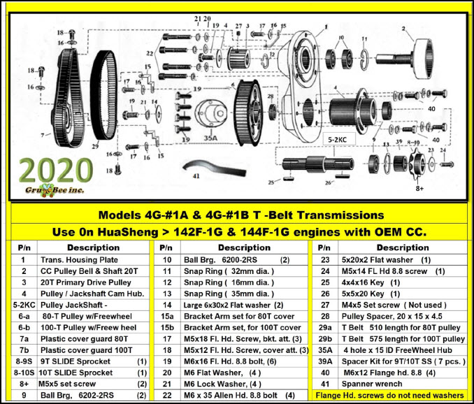
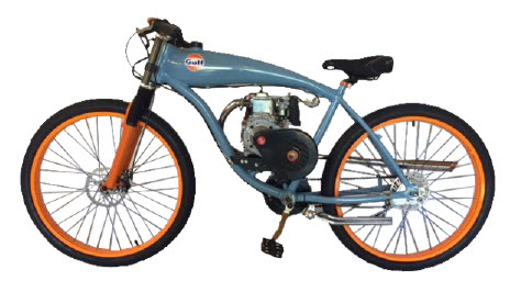
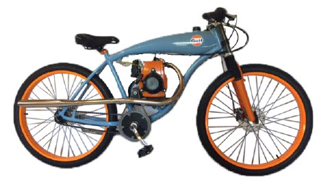
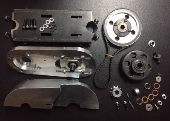
4G Model #1A & 1B T-Belt Transmission Kit |
Reference web sites; Canada; www.motorizedbicycle.ca USA www.grubeeinc.com
The original T belt drive transmission, copied by others but never duplicated. |
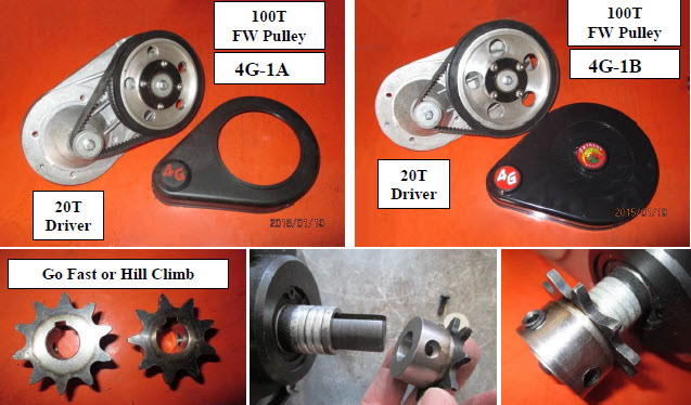 |
4G kits come with 9T and 10T multi position drive sprockets: Choose what you need. |
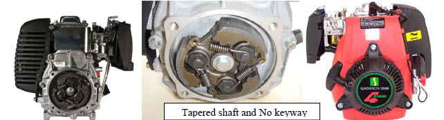 |
4G Model 1A and 1B Trans. fit HuaSheng 142F-1G 49cc & 144F-1G 53.5cc engines: These 2 HuaSheng engines come with a reliable 3 shoe centrifugal clutch on a tapered shaft.
BEWARE OF FAKE ENGINES WITH NO ID PLATE & NO EPA EMISSION STICKER!
4G WARRANTY IS VOID IF USED WITH A FAKE LOOK-A-LIKE ENGINE. |
Honda GXH50 & HS engines with straight 5/8”x 1 ¼”- tapped ¼-28 with keywayed shafts must use 4G 2D trans. ( 4G-1A and 4G 1B Trans. will not fit 5/8” straight shaft engines. ) |
|
|
| |
 |
 |
|
 |
READ THIS MANUAL THROUGHLY BEFORE ATTEMPTING TO USE THIS PRODUCT: |
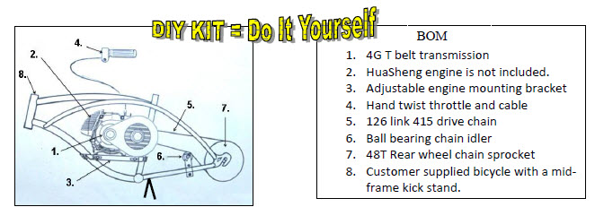
This is a DO IT YOURSELF PROJECT: Mechanical Aptitude is Required: Please do not attempt this project if you do not have a good understanding of gasoline engine maintenance, hand tool usage and mechanical mechanism operation. It is common belief that most laws stipulate that a motorized bike with an engine less than 50cc; having less than 2 hp and going no faster than 30 mph is legal to operate without license, registration, or insurance. For complete legal details you should contact your local state authorities as we cannot be responsible for knowing all state and local laws….. |
|
|
 |
We have many drive ratios and rear wheel options available: |
|
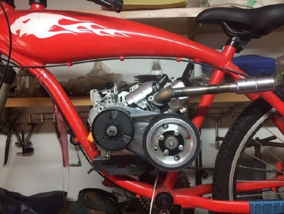
OPERATION: When the engine is at about 3000 rpm the 3 shoe centrifugal clutch on the crankshaft will latch up with the 20T pulley drum bell. The 20T drive pulley is supported on a shaft with 2 ball bearings. The 20T drive pulley on the drum bell transmits rotational torque to a larger driven pulley which can be either 80T or 100T. The driven pulley being affixed to a jackshaft then transmits engine torque to a drive chain sprocket which can be 9T or 10T. A heavy duty 415 size chain drives a rear bike wheel sprocket which can me 44T, 48T or 56T. The driven pulleys on all 4G-1A, 4G-1B and 4G-2D transmissions have an integral Freewheel Assembly that allows easy pedaling while in engine off people pedal mode. |
 |
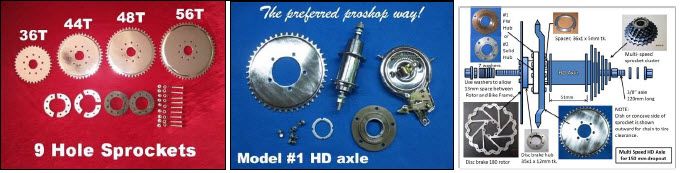
#2 below is a 9 hole 48T clamp to spokes sprocket. > 36 to 56 Teeth sprockets are also available. |
|
|
| |
 |
| |
 |
| |
 |
| |
 |
| |
 |
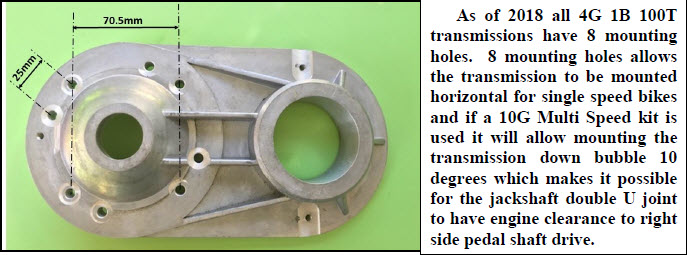
NOTE: 10G Multi-Speed requires installation on the Gru-Bee GT2A or GT3A frame with built in gas tank and pedestal mount which will give a 3 point engine bracket lockup. |
|
|
| |
|
| |
 |
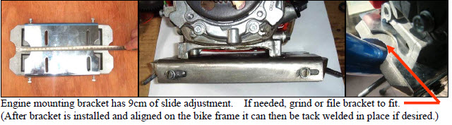
If desired the steel engine mounting bracket can be welded in place after final fitting has been made.
Some fitting enhancement may be needed to fit down tube by grinding out the bracket mount curvatures. |
 |
| |
Your Donor Bike Requirements for 4G Kit #1A & 1B; |
| |
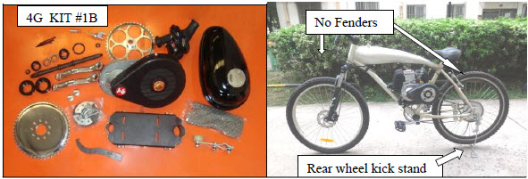
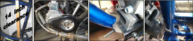
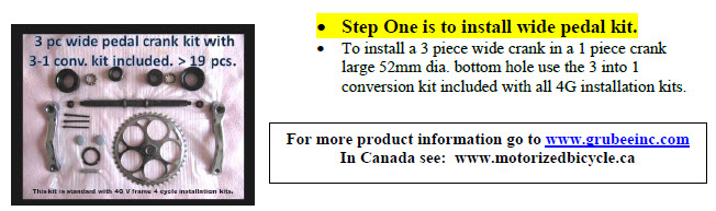
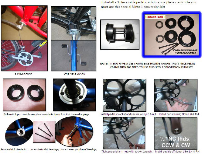
| A cruiser bike with a 28 to 38mm dia. front down tube and a 28mm dia. seat tube works best. Be sure to have a mid-frame kick stand or a rear wheel lift kick stand so the rear wheel can be up when staring the engine. Running the engine with wheel up allows for a spinning wheel engine warm up. Old style 26” Crusier type bikes with heavy steel frames work good. Do not use a bike with wheel fenders as attach struts can come loose and get jammed in the spokes while riding causing rider injury. Your 4G Kit includes a Wide Pedal Crank with 3 in 1 conversion that allows installation into 52mm dia. large bottom holes made for a one piece crank or can also fit small bottom holes made for a 3 pices pedal crank. It is essential that your donor bike have both front and rear brakes for safe operation but a disc brake on the rear wheel cannot be used. Using a bike with a coaster brake is not recommened because if the pedal chain breaks you have no brake. Do not ride with inadequate brakes! The doner bike needs at least 14” clearance between bottom hole and top tube. Do not use bikes with cheap made axles and front forks. Do not use wheel fenders as they can cause danger if they come loose and the stays get intangled with spokes causing rider to enjoy a flying leap over the handle bars. Speeds in excess of 25mph is not recommended due to a bicycle’s lightweight inherent design.. The smaller the rear sprocket the faster the top speed. Going faster than a bicycle was designed to go is foolish. #1HD or #2HD axle kit is recommended for more lasting endurance. When riding always wear a helmet and abide with local and state laws. Remember, you are the designer and assembler of your own motorized bike so use good engineering practice and common sense when making your component selections and applications to a donor bike. The end user or the installer becomes the prime vehicle manufacture and accepts all laws of the land which includes product liability. Do not use or buy this product if you expect otherwise. |
 |
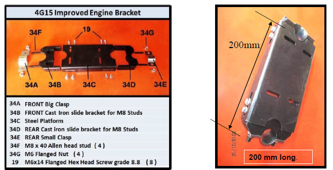
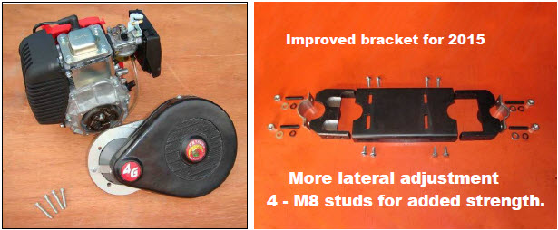
| Front and rear bracket fit should look like this. Length adjustment is from 17cm to 25cm. |
|
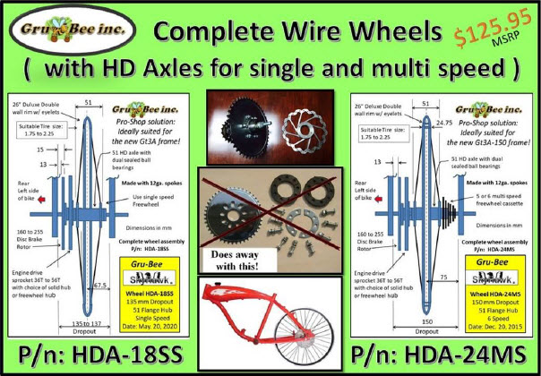 |
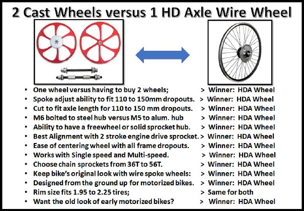
Use our HD axle rear wheel for a precise installation and long life enhancement: |
| |
|
| |
 |
| |
 |
| |

|
| |
 |
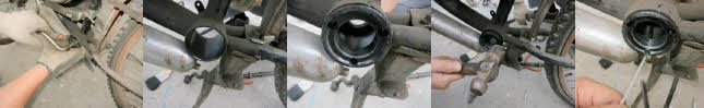 |
| Remove old crank & chain; Insert hubs in both sides and hammer tap in place while lining up 3 bolt holes. |
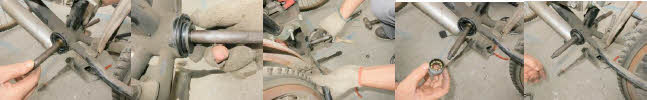 |
| Insert crankshaft; Install Bearing cage on right side and tighten; Install bearing cage on left side and adjust. |
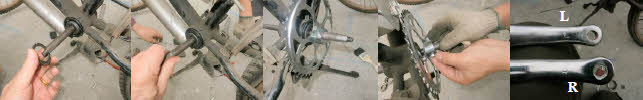 |
| Install lock ring left side: Adjust shaft rotation & lock in place: Install sprocket on R side: Note letter on arms: |
|
Install pedal arm with L on left side and R on right side viewing as if setting on the bike seat. After final
adjusting shaft rotation secure lock ring in place: Install 2 pedals knowing that the Left side is CCW left hand
thread and Right side is CW right hand thread. Re-install pedal chain in reverse procedure to that of removal. |
This SkyHawk 4G transmission has US patent pending # 11428539-4173.
These instructions are copy-righted, DO NOT copy for commercial use without our written permission. |
|
|
| |
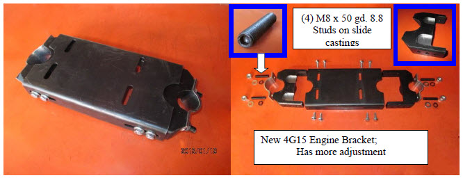 |
| Fore and aft slide adjustment; Position the bracket to best fit engine and frame: |
| |
Step 2. Engine Mounting: |
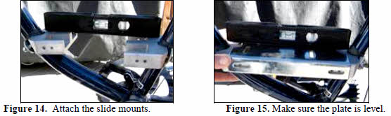
| Attach engine to bracket plate using M6 x 16 Socket Allen Hd. bolts included in your I-Kit. Remove 8 side bolts from the engine mounting bracket and separate the plate from the 2 end cast iron slide mounts. Attach the 2 slide mounts to the bike frame; (Figure 14.). If the frame down tube is too big for the slide mount opening, grind out the curvature and or you may need to remove, drill and tap to reposition the studs out ward. Make sure that the engine mounting plate sits in a level position (Figure 15.) and lines up with the side holes. Lift the plate off the mounts and install it on the bottom of the engine using 4 > M6 x 16 cap screws & washers. |
| Engine must set level for best carburetor operation. |
 |
| Be sure to measure thread depth in the engine first. Tighten bolts finger-tight only, for right now. Set the engine with 4G transmission pre-attached on the 2 castings. Remove the master link from the engine drive chain with the needle-nose pliers. Drape the chain over the bike rear wheel sprocket and over the 4G transmission output sprocket. Pull the chain taut. Check the alignment of the chain from the rear of the bike. The chain should be in alignment with both sprockets. Adjust alignment by sliding the engine left or right on the engine plate. If you cannot get the chain aligned properly, you may have to remove the bike wheel drive sprocket and change its orientation (from concave-in to concave-out. Once you are satisfied with the engine drive chain alignment apply 242 Blue Loctite and wrench tighten the 8 bracket side bolts and the 4 bolts on the bottom of engine. Be very cautious when tightening these bolts. They are grade 8.8 and will strip the threads in the cast iron if you over tighten them. (Over tightening is not covered under warranty). At this time, you can install any special muffler you intend to use |
Step. 3 Install transmission on HuaSheng engine |
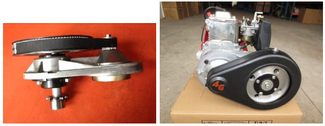
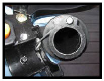
| Install the T Belt transmission on the engine with the drum bell fitting over the 3 pole CC rotor and aligning threaded holes for (4) M6x35 cap bolts & washers. Make sure the transmission plate seats firmly and flush in the engine PTO flange cavity. File or fit if required: Final fitting use 242 Lock-Tite on all (4) M6x35 bolts |
|
|
|
 |
| Disclaimer Note: Please remember this is a DIY Parts Kit made for adults for use with a HuaSheng engine as hobby or for personal pleasure: Failure to understand or carry out installation instructions is not the responsibility of the components manufacture nor of the selling distributor or dealer. Common Sense, Engine Knowledge, and Mechanical Aptitude are required along with a love passion for small engines and motorized bicycles. Field Modifications to install and operate may be necessary. The end user or assembler must take self-responsibility of his own recognizance to design and make his own finished product. Operating a motorized bicycle involves risk of bodily injury. Buyer accepts full responsibility for any and all vehicle operations that may lead to personal injury, economic loss, social distress, other losses, costs and damages. Neither China GAS,/ Gru-Bee inc. nor the selling WD Distributors can be held responsible for injuries and / or damages resulting from operating a motorized bicycle with this engine installation kit. This kit is not recommended for use by persons under 16 years of age. Obey all traffic regulations. Always wear a helmet while riding. Remember that you are riding a motorized bicycle and other traffic may not be able to see you. Never operate your motorized bicycle on a pedestrian through way or sidewalk while the engine is running. Never operate your motorized bicycle in an unsafe manner. Check local and state laws before riding on state highways or city streets. A rewarding and joyful challenge can be found in designing a custom installation of your own. Remember, a quality installation is paramount to safe usage and your long term satisfaction. You may find many uses for this 4G Parts kit from stationary machinery to off road go-carts. Have fun and good luck: |
|
|
| |
 |
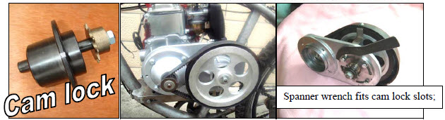 |
| Use spanner wrench to adjust belt tension; Tighten 4 bolts securly on cam lock after adjusting belt tension. |
 |
| |
 |
| |
Step 4. Install kit supplied 9 Hole Sprocket, 56T, 50T, 48T or 44T”. |
| Position with convex side inward, teeth outward to give better chain to tire clearance. Affix with 9 bolts through 2 half moon bearing plates on top of 3 banana plates bearing on rubber gaskets next to wheel spokes. |
| |
| Use locktite on the threads and torque evenly to produce a sprocket installation that does not wobble. If the center hole needs enlarging to fit the axle hub use an engine lathe to gain best cutting accuracy. If hand grounding with a Dremel tool mark a circle out line using a round pattern such as a piece of PVC pipe and a black marker so your cutting is evenly round. Use of the Model #1. or Model #2 HD axle kit avoids all these problems but is an extra cost option available from your Skyhawk 4G kit dealer or distributor: |
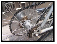
| How to install a standard clamp to spokes sprocket on a caliper brake wheel. |
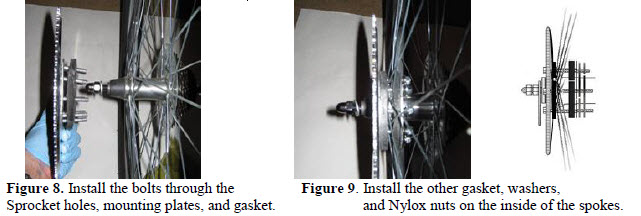
| First step will be to disassemble the sprocket mounting assembly included with the kit. Apply a light coat of grease or anti-seize compound on fastners. This will keep water and salt out of the threads and allow for easier removal of the sprocket mounting assembly in the future. Hold the engine drive sprocket with the concave side facing you and push the bolts through the holes. On the convex side, fit the set of three bannana mounting plates on the bolts. Then, fit a rubber gasket on the bolts (Figure 8). Place the sprocket assembly on the wheel. In order for the inside rubber gasket to go around the axle cut one side between the holes. . Reach inside the spokes and fit the gasket on the bolts. Install the 3 bananna plates first and then 2 half moon plates on top. Install lockwashers and nuts with a cross or star pattern tigthening process. You will find a ratchet and long extension helpful to do this. (Figure 9). |
| |
 |
| Make sure the sprocket is centered on the axle. Once the sprocket is centered, tighten all bolts in a "star" pattern. Tighten the 9 bolts until the gap between the rubber gaskets closes completely. Spin the wheel while looking at the edge of the sprocket. If there is little or no wobble, the sprocket is aligned with the wheel. It is important that the sprocket be installed correctly, or the chain will jump off. Install the rear wheel on the bike. Prop up the bike so the rear wheel is free to spin. Place a ruler or straight edged on the chain stay bar and push it towards the sprocket until it almost touches (Figure 11). Spin the bike wheel and check for any sprocket wobble; Loosen and re-tighten sprocket bolts in sequence to eliminate wobble. |
|
| |
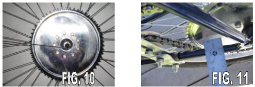 |
Figure 10. Make sure the sprocket is centered by measuring concentricity from teeth to axel hub.
Figure 11. To detect wobble use a ruler to help true your sprocket. Loosen and retighten bolts till true. |
| |
Sept 5. Install Chain after first test starting engine and setting idle speed; |
| The chain you receive is longer than necessary in order to accommodate most bikes. You may need to remove the appropriate number of links to fit. To estimate length required place the chain around both drive sprocket and wheel sprocket griping in one hand while pulling chain tuat with your other hand. Mark chain location to make the master link splice. |
|
| Figure 16. After splicing the chain together it should be just loose enough to slip off the sprocket. |
| |
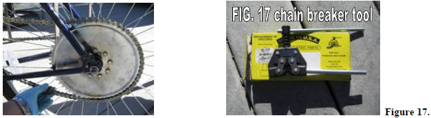
| You will need to estimate the proper length for the chain. The chain will need to be loose enough to slip off the rear sprocket, (Figure 16). You will want to be able to remove the chain later without having to remove the rear wheel. When the chain tensioner is installed, the chain will not slip off on its own, assuming everything is aligned properly. Keep in mind that the chain will be one link longer when the master link is re-installed. Once you have decided on a chain length, mark the link to be removed. You can use a "chain breaker" tool (suitable for and HD 415 chain) to remove the link. (see Figure 17 ). |
| |
| Note: If you don't have a chain breaker, you can use a blunt nail and hammer (carefully) to punch out the link pins. Do this operation on a block of wood. Drill a hole in a block of wood and place the link on the wood with the link pin over the hole. Tap one link pin until it is halfway out. Then work out the other pin from the same link. Install the master link on the chain and check to see if the tension is correct. If it is too tight, you will have to install a link using a hammer and block of wood. |
| |
| Install the master link on the chain. Push the master link (with pins) into the chain from the left side of the bike. Install the idler or chain tensioner. Make sure that the chain tensioner wheel rides on the outside of the chain as shown in the photo #25. If you install the chain tensioner wheel on the inside of the chain loop, the chain will pull away from the sprocket, and slip off. The chain should move about ½” up and down from a point midway between the seat tube and rear wheel. It should not bind excessively when the rear wheel is turned. If it binds, check the chain tension and sprocket alignment. Do not start the engine until you can rotate the wheel by hand without the chain binding or slipping off. A binding chain under full load can break sprocket teeth or cause other damage! |
| |
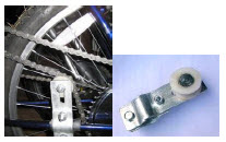
Figure 25; Chain idler with ball bearing pulley wheel:
Adjust chain tension with chain idler mounted on bike wheel strut or chain stay. At middle span adjust to ½”” chain deflection. Install chain idler bracket with pulley on inboard side as shown; ( See Fig. 25 & Fig 26 ) |
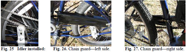
| There is not a chain guard included with this kit. The end user can fabricate a sheet metal guard as required for his own form, fit and function. One option is use a 2 cycle engine chain guard available from your WD or selling dealer and modify it as required. Install the chain guard as shown (Figures 26 and 27). The chain guard has a front strap built into it. For the rear strap, use the strap that comes with the guard. Make sure that when you are riding, you don't have any long clothing or other belongings or body parts that could get caught in the chain. |
 |
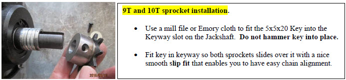
Step 6. CHAIN ALIGNMENT; 9T and 10T slide sprockets can be moved by repositioning the spacers on the output shaft from outboard side to inboard side to allow perfect chain alignment. Tighten set screws. Use 242 Loctite. |
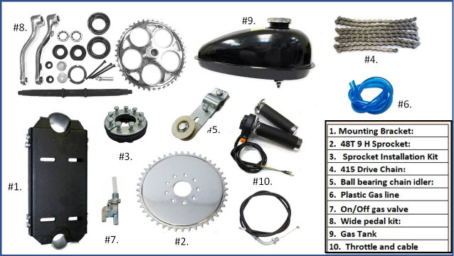
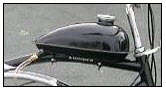 A) Install tank on top tube and hook up gas line to carburetor. Use strip of rubber from an old tire tube to cushion tank on top tube. Even though the tank in our installation kit has zinc plating inside to help prevent rust it is a good idea to have your tank KREEMED before installation to prevent A) Install tank on top tube and hook up gas line to carburetor. Use strip of rubber from an old tire tube to cushion tank on top tube. Even though the tank in our installation kit has zinc plating inside to help prevent rust it is a good idea to have your tank KREEMED before installation to prevent
possible rusting during times of long term non-useage such as winter time storage. This product is available from motorcycle dealers by the trade name of “KREEM” www.kreem.com |
B) *NOTE: A Gas Filter is in the tank petcock valve. If engine runs poorly clean the valve filter as residue from the tank may have clogged it. Use the EPA black rubber fuel line supplied with this I-Kit.
C) Unlike 2 cycle engines don’t forget this is a 4 cycle engine and requires frequent crankcase oil changes to ensure long engine life. 2 cycle engines have a gas / oil mix system and have no crankcase oil reservoir; Refer to the engine owners manual for oil change and maintenance recomendations. If you have a 2012 or later model HuaSheng engine you may find the carb. is not allowing the engine to run properly. This is likely due to the elimination of the air/idle screw which means you may need to find an old model carb. |
| |
Install throttle on right side handle bar. Drill 15/64” hole in the handle bar to accommodate throttle housing lock pin. Measure deepth of handle and pin location to locate the spot to drill handlebar. Use center punch to make a dent to start the drill. Make sure handle does not bottom out on the handlbar. |
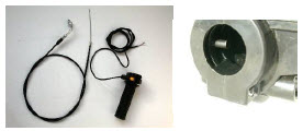
Step 6. Figure: 22. Throttle cable installation: |
 Remove top plate on throttle housing: Pull cable outward and insert thru open threaded hole in throttle housing. Connect cable metal barrel into twist grip slot as shown in Fig 22. Insert twist grip in grooved slot on the throttle housing. Slide the throttle assembly on to right side handlebar and match up peg with the 13/64” drilled hole. Tighten goose neck cable connection. Install the top plate on the throttle body and put a small amount of loctite on the screw and tighten securely. Pull slack out of cable and attach to carburetor. Use plastic ties to hold cable out of the way making sure enough loop slack is given to turn handlebar both directions full swing. Throttle kill switch has 2 wires that plug into the engine switch wires. Unplug and insert the 2 throttle wires in series. Leave red engine switch knob in the “OFF” position or engine will not stop when using the handle bar throttle kill button. It makes no difference which wire goes where as throttle button switch is a normally open switch. Remove top plate on throttle housing: Pull cable outward and insert thru open threaded hole in throttle housing. Connect cable metal barrel into twist grip slot as shown in Fig 22. Insert twist grip in grooved slot on the throttle housing. Slide the throttle assembly on to right side handlebar and match up peg with the 13/64” drilled hole. Tighten goose neck cable connection. Install the top plate on the throttle body and put a small amount of loctite on the screw and tighten securely. Pull slack out of cable and attach to carburetor. Use plastic ties to hold cable out of the way making sure enough loop slack is given to turn handlebar both directions full swing. Throttle kill switch has 2 wires that plug into the engine switch wires. Unplug and insert the 2 throttle wires in series. Leave red engine switch knob in the “OFF” position or engine will not stop when using the handle bar throttle kill button. It makes no difference which wire goes where as throttle button switch is a normally open switch. |
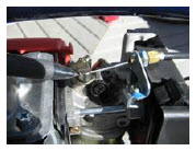 Carb. Cable and Choke Hook Up: Hook up the throttle cable to the throttle arm on the carburetor as shown. Ensure that the throttle arm returns to the idle position after you let go of the throttle grip. The idle position is when the throttle arm touches the black plastic idle screw. Some engines differ in this area so field modification may be required on the part of the installing mechanic. Test Start engine without chain installed and tune rpm to optimum idle condition to ensure centrifugal clutch is not engaging at idle speed; To start: set choke; and open air cleaner baffle lever and pull on rope: After starting progressively remove choke and let warm up. After test starting, kill the engine and proceed to complete the installation process. If engine fails to start check fuel line; ignition spark and kill switch; Carb. Cable and Choke Hook Up: Hook up the throttle cable to the throttle arm on the carburetor as shown. Ensure that the throttle arm returns to the idle position after you let go of the throttle grip. The idle position is when the throttle arm touches the black plastic idle screw. Some engines differ in this area so field modification may be required on the part of the installing mechanic. Test Start engine without chain installed and tune rpm to optimum idle condition to ensure centrifugal clutch is not engaging at idle speed; To start: set choke; and open air cleaner baffle lever and pull on rope: After starting progressively remove choke and let warm up. After test starting, kill the engine and proceed to complete the installation process. If engine fails to start check fuel line; ignition spark and kill switch; |
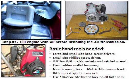
Check engine oil level in crankcase; New HuaSheng engines have no oil! Read the owner’s manual.
Use 20 or 30wt. oil to full line. Use of an oil drain hose is recommended: Change oil every 200 to 300 miles; Remember: This is not a car engine that can go 5000 miles between oil changes: |
| Install drive chain and connect master link; Before restarting engine elevate the rear wheel and check chain and wheel alignment; Check chain idler and chain for smooth operation; |
| |
Step 7 |
- Practice starting and running operation in a vacant parking lot or a safe place until you are familiar with your moped operation before going on public roads.
- Ensure that the fuel valve lever is in the “on” position (parallel with the fuel line ).
Check the fuel line to make sure gas is getting to the carburetor.
Before you start the engine, test the bike brakes. Set choke to ON position, Rope pull start the engine with rear wheel elevated on a mid-frame kick stand; Allow warm up time and release choke.
- It is best to pedal your bike until moving and then give the engine progressive throttle advance.
- Twist throttle handle progressively; when the engine reaches 3000 rpm the centrifugal clutch will engage.
- If it feels like the engine is "over revving" while you ride, you’ve reached the max. speed allowed by the gearing ratio which means you may want to change sprockets.
- To stop, shut off throttle and apply brakes. To kill engine; push kill switch button on throttle handle.
- If you have a 2012 or later model HuaSheng engine you may find the carburetor is not allowing the engine to run properly. This is likely due to the EPA required elimination of the air idle adjustment screw which means you may need to find an old model prior 2012 made carburetor that still has this adjustment feature.
|
 List of Tools and Materials: List of Tools and Materials:
SAE & Metric open end wrench set,
Ratchet & metric socket set;
Needle-nose pliers
Vise-Grip pliers
Metric Allen wrenches
Phillips head and slot head Screwdrivers
Ruler or tape measure.
Permanent marker ("Sharpie" or equivalent)
Drill with 3/32" and 15/64" (or 1/4") bits
Cable Zip Ties
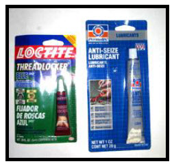
Medium strength thread locking compound "Blue Loctite" #242 or equivalent.
Note: thread locking compound can melt certain types of plastic, so use on metal only. |
Special Order Optional accessories: |
 Optional Gru-Bee HD Rear Axle Kit Model #1 with freewheel flange made for attaching 44T, 48T or 56T sprockets. HD Axle #1 allows the wheel drive sprocket to be bolted directly to a freewheel hub that screws on the HD axle with CCW threads. Thus, Sprocket to Spoke clamp installation is eliminated and allows bike pedaling engine off without any chain restriction. HD axle wheels prevents broken spokes and gives true alignment for a pro-shop set up: HD Axle has sealed ball bearings with double row balls to ensure long life and heavy duty operation. NOTE: Using the optional dual brake cable throttle allows for a 3 brake system. For hill climbing use a 9T Sprocket with 56T rear sprocket; For highest flat land speed use the 10T drive sprocket and 44T rear sprocket. Heavy riders use 10T/48T rear sprockets and hill climbers use 9T/56T. Going fast is not a good idea if your bike has poor brakes, worn tires or if you are an inexperienced rider. Optional Gru-Bee HD Rear Axle Kit Model #1 with freewheel flange made for attaching 44T, 48T or 56T sprockets. HD Axle #1 allows the wheel drive sprocket to be bolted directly to a freewheel hub that screws on the HD axle with CCW threads. Thus, Sprocket to Spoke clamp installation is eliminated and allows bike pedaling engine off without any chain restriction. HD axle wheels prevents broken spokes and gives true alignment for a pro-shop set up: HD Axle has sealed ball bearings with double row balls to ensure long life and heavy duty operation. NOTE: Using the optional dual brake cable throttle allows for a 3 brake system. For hill climbing use a 9T Sprocket with 56T rear sprocket; For highest flat land speed use the 10T drive sprocket and 44T rear sprocket. Heavy riders use 10T/48T rear sprockets and hill climbers use 9T/56T. Going fast is not a good idea if your bike has poor brakes, worn tires or if you are an inexperienced rider. |
|
|
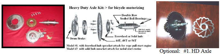 |
| Threaded CCW 36-1 Freewheel sprocket hub and disc brakes give that Pro-shop touch. |
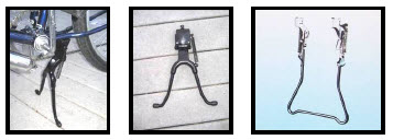 Most swing down single rod type kickstands will eventually fail under the additional weight of this engine kit. It best to replace it with a mid frame wish bone type kick stand or a rear wheel left stand. This allows engine starting with rear wheel up. Most swing down single rod type kickstands will eventually fail under the additional weight of this engine kit. It best to replace it with a mid frame wish bone type kick stand or a rear wheel left stand. This allows engine starting with rear wheel up. |
Things to remember: |
- Drive Chain should be checked for streching after riding for several days;
- Gas tank interior should be coated with “Kreem” for lasting protection. www.kreem.com
- If any debris gets into the carburetor, it may cause the float valve to stick open and leak gas. If this happens, the fuel will run out through the overflow tube until the fuel tank is empty. To remove the debris, you will need to remove the float bowl and blow compressed air into the brass tube on the left side of the engine, just above the carburetor.
- To remove handle bar grips from our donor bike apply compressed air nozzele under grip and twist off.
- Throttle cables can strech over time. Adjust as needed.
- Good brakes are a must. HD axle model #1 is recommended: Coaster brake bikes are not recommended.
|
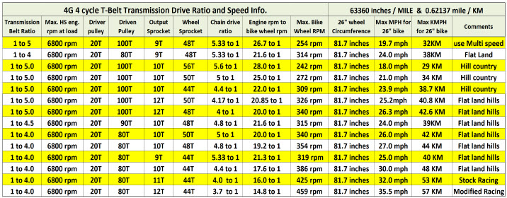 |
HOW TO CALCLATE FINAL DRIVE RATIO: |
| To calculate final drive ratio you have one constant, the 20T belt drive pulley; Divide 20 into the driven pulley’s number of teeth. ie: 80/20 = 4 Divide the jackshaft output drive sprocket number of teeth number into the rear wheel sprocket teeth number. ie: 48/10 = 4.8 Now multiply both quotients together, ie: 4 x 4.8 = 19.20 to one. |
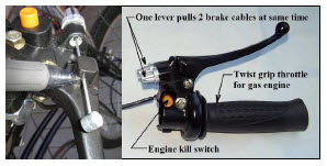 Installing a 2 Brake Cable Throttle: Installing a 2 Brake Cable Throttle:
Loosen clamps and pull the brake cables out of sheathings: Feed brake cables through the holes in the throttle grip lever. (Fig. 23 ) and then back through the nipple housings into the cable sheathing. Lever boss holes are drilled for standard diameter brake cable. If you have oversize brake cable, you will have to enlarge the holes slightly with a drill. If more lever stroke is needed you can file off some of the leading front edge of the lever where it seats. |
Thank you and Congratulations:
You have just purchased an outstanding DIY parts kit; DIY means “do it yourself”. We hope you enjoy what you end up with. If you’re wondering why we have so many options it is because all markets are different and personal opinions differ. Some folks require the cheapest way and some require the premium way. The end user or installer must decide to suit his own needs. Mechanical aptitude and hand tools are required. Be sure to apply Loc-Tite 242 thread lock to all fasteners and final torque to ensure all are tight and secure. It is best to have a qualified automotive or motorcycle mechanic do the installation if you lack the necessary experience and talent. Please use caution when operating a motorized bicycle and follow all federal, state and local laws: |
 |
 |
10G Multi Speed right side drive: Shift gears like a motorcycle! |
 |
2020 NEW PRODUCT ANOUNCEMENT: 5G-8M T-Belt Drive 79cc 4 Stroke |
| |
 |
WWW.GRUBEEINC.COM |
 |
